Tuesday 8 December 2009

Animation

The first part of the animation of the engine was a two person effort from Myself and Matt working on getting one cycle of the engine complete, after that we planned to put it on a continuous loop so it would always go round.


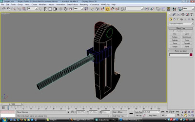
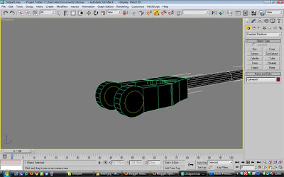
The first task was to animate the arrangement that spins around as you can see in this next screenshot with the two sphere hanging from it:


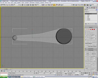
One main problem we discovered when rotating this round was that the base of this part on the actual engine was round and the base of the part in 3d Max was oval. This was a problem which I don't know whether it came form importing the object into the scene when the objects were collated or a minor oversight when the item was created but none the less, I used my best efforts to amend it, it didn't go perfectly, but I felt much better after selecting the polygons at the base of the object and scaling them one particular way, but because of the way it was moulded, i found it awkward to get it exactly right. Then it was just a case of Autokeying it rotating, I used the 'Centre to Object' Button on the Pivot point Edit tool and then simply moved the pivot point downwards to the base of the object. I used the video we recorded to calculate it would need 90 frames to turn on one full rotation at 30 frames per second (fps). So I made sure that one full rotation had been completed on the 90th frame.

Wheels

Sorting out the animation for the wheels was fairly easy, it consisted of grouping the items contained within the wheel together:


and setting the pivot point in the correct location and using the rotate tool to spin them round, again, i used the video to estimate around 6 seconds for one full rotation for the wheel, so I ended the animation at the 180th keyframe for one full rotation. rotating both of the wheels together saved me some time because it meant i only had to animate the wheels once instead of turning them separately.

Machine Arms

To start with I animated the arm at the very far side of the machine first simply because it was easiest to start with this one in the side view.


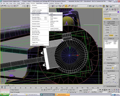
In this first instance I used 'Set Key' to keyframe the animation to see how smooth it would be, it turned out to be ok but i learned that Autokey would be a much better bet for this, trying the Euler function for roatation would've been first choice but trying to master this proved to be too difficult in the timespan we had left to complete the assignment in preperation for the presentation. Again timing was used from the engine video to gain the most accurate speed for the movement of this object:


'S' Shaped Arms

The essence of moving these arms is very simple, the most important part is getting the pivot point dead centre of its rotating pivot.


once the pivot point was correctly located, we checked to see whether it was rotating on the correct point and once it was, It was just a case of doing the same with the other 'S' shaped arm and rotating them together using the 'Autokey' feature as before.

Moving the main arms connected to the 'S' shaped arms was not such a difficult affair, with the Autokey function selected, every 10 frames i moved the arm using the 'Left' viewport to place the centre of the rotating point with the 'S' shaped arms in the hope that it would move with it smoothly and flow.


next, i viewed the machine from the top so that i could select the right bits from the left hand side of the machine so they could be used for the right hand side:


the easy job was cloning them over, but the harder task was to get them to move at separate times, at first in just trying to move the key frames around, the cloned arms kept wanting to catch up the previous animation and therefore sped up to compensate, eventually Matt and I overcame this by extending the timeline and moving the keyframes along and copying the last few keyframes and placing them at the beginning of the timeline.


Linkage

This was probably one of the more difficult parts of the animation and getting it to look smooth and flowing naturally, Matt and I tackled this part to the best of our efforts using Autokey and minor movements to get the linkage into place each time one of the bars moved and trying to get the parts that join to stay together, the first task was to attach the items required to move in the linkage so they become one item:
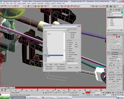


the animation again was just careful movement through Autokey to get everything into line and to where it should be, this was probably the hardest thing we have come across so far with the animation side of things.
After we managed to complete this difficult task, we had one full rotation of every moving component we used the curve editor to select 'Cycle' so that the engine would just be on one continuous loop.

Sunday 6 December 2009

Grouping the Parts

Well job one with this task was to import all the files into one scene - the sheer complexity and amount of polygons i think almost overloaded the PC, the filesize turned from an already large 33mb file into a gigantic 100mb file, the core 2 quad PC's in the labs had a job to handle it.
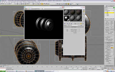
Keeping the task in mind, we piece out the items separately looking at the scales and overseeing any potential problems with grouping and placing the objects together. upon Importing, there were several issues to be overcome, we had the issue of different peoples parts they had created some being massive and some being tiny, we had overlooked scale to a vast majority and had to sort out these issues quick, we couldn't spend long time dealing with scale issues because it would eat into our vital animating time, but none the less, it was a job that had to be done, so me and Matt franklin, another member of the group took on the task of sorting out the engine parts.


in the picutre above, we have scaled most of the parts and put them into place, this was quite a big task in itself but with two of us, it happened a bit quicker, however in the picture there are still some major things to be dealt with, such as the bars not linking up, small parts from the engine which had been overseen initially now needed to be created to finish off this part.


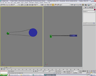
Above is one of the arms that rotates on the rotation of the wheel, however the part in question consisted of about 40 smaller parts that needed to be grouped together and the bar at the end needed extending to meet its point, so it needed to be ungrouped, rotated so that it could be scaled and then moved back down so we could check it was the right length:


Grouping the Items back together after scaling:


Adjusting the pivot point:


Putting it back in place:


Adding the wheels:


Next, we found that the u bracket around the linkage I had created was far too wide compared to the actual linkage which was a silly error to make seeing as I had created both of them, so back into the version I had of this part to quickly edit the width and re-import it back into the scene:


Next came the business of adjusting the pivot points preparing for animation on the parts we knew were finalised, so not to delay, we edited the pivot point onto the U-bracket we just edited:


This picture shows you where the part is now rotating thanks to editing the pivot point:


The U-bracket was cloned and twisted to be used for the one underneath;


Adjusting the brackets into position:


Adjusting the pivot point of the big linkage that I created:


Developing a missing part on the side of the machine, consisted of a few cylinders, editing the vertices to taper the end and rotating one of the other cylinders because it rides up at an angle:


Putting a taper on the edge:


rotating the next cylinder up at the required angle:


Created a rectangle and then rotated it round so it was in a diamond shape and curved the edges using the edit vertex option:


placed into position on the front of the cylinder and attached:


Cloning one of the arms to use as the cylinder that links to this part:


extra cylinder to add on where the cylinder moves in:


wireframe birds eye view of the engine as it currently stands:


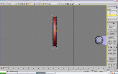
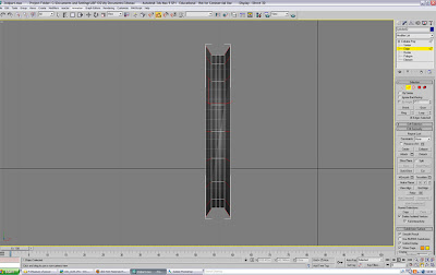
One obvious problem and we don't know where it occured but there was an issue with the wheel which couldn't seem to be sorted using meshsmooth or turbo smooth so unfortunately parts of it had to be recreated:


you can see the jagged edges which unfortunately couldn't be removed to our knowledge, you can see a render of the recreated wheel in a few screenshots time.

Next job was to edit the base as and where we had to make it as close to the shape of the real life model, here are polygons seletced ready to delete:


More editing of the base:


Creating the hole beneath these parts and trying to get the shape right using pictures to compare:


Creating the second hole:


cloning the linkage and moving the arms into position for the linkage in the middle of the machine:


and here is a render of the engine as it stands at this point:

Saturday 5 December 2009

2nd Part

Linkage mechanism
the next task I was assigned to do was the little linkage mechanism and the two pulleys that rotate the large belt at the edge of the machine

Picture of the linkage for reference (you can also see the small pulley and belt I have to model as well):


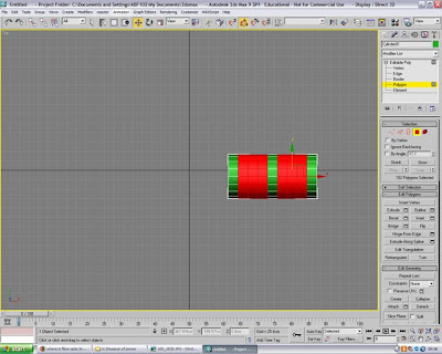
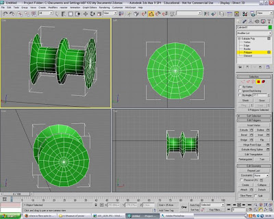
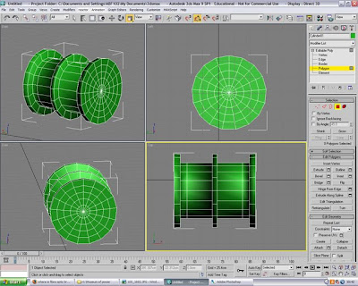
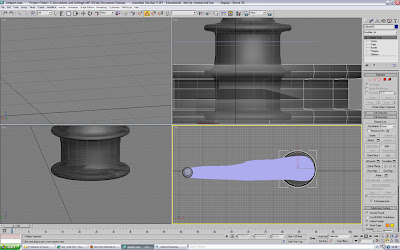
So the first job I took on was to create the pulleys and belt. This consisted of starting out with a cylinder, enough polygons in the height so we can select two sections to scale smaller:


And then scale the selected parts down so it leaves a shape similar to this:


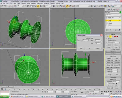
Using the connect edges tool I added some more edges in to manipulate the shape further:


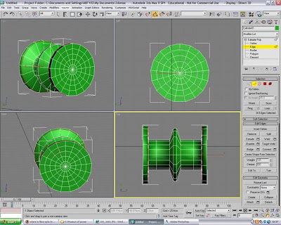
Enlarged them so they matched the size of the outer edges


Edited it a little further til it represented the shape I wanted to use:


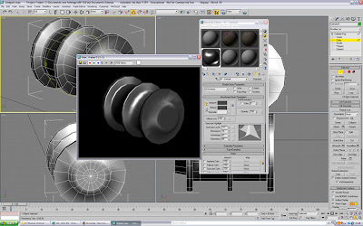
here is a little render of this part


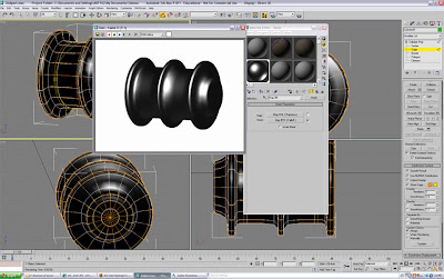
Using Nurms to smooth and changing the material slightly


Looking very nice but just to render this little part, it took around about 30 seconds which is way too much considering this is a very small part of the final scene so I took the raytrace effect off and it took it down to a much more acceptable 3 seconds! still leaving a nice result


The Big pulley


the big pulley is essentially the same as the small pulley but I still created it separatelt because it did have minor differences I wanted to capture So using a cylinder:


again I selected the inner polygons and scaled them smaller:


Added two more edges using the loop and then the connect tool:


manipulated the added edges to put a slight curve at the top:


Editing the belt

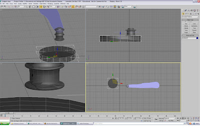
Next I placed the big pulley at the end of the very rough belt i had created so now that I could shape it round the two pulleys i had created:


The first job was to just pull the vertices of the very rough belt to the actual shape around both of the pulleys


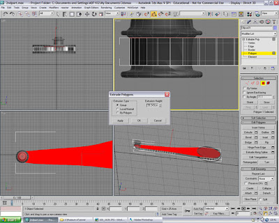
The belt then needed to be converted to an editable poly and then extruding to the width of the inside of the pulley:


The final belt with the inner polygons deleted to just leave the outside ring:


Linkage

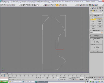
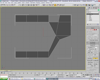
The linkage part of this was slightly harder as the shapes are more diverse and complex in the linkage part, I started off by creating a shape using splines similar to the linkage shape and converting it into an editable poly:


Now unfortunately after this part I used a PC where the print screen button didn't work unfortunately leaving me without a few screen shots of creating this part, but here is a couple of pictures of the finished article and I'll explain what I did


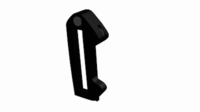
this picture here is showing the finished part from what I was creating in the pictures earlier, it is basically the 3d poly after having been extruded and the edges capped because it had one side that was open and slightly modifying the shape so it correctly matched the shape of the original part on the engine. the only other thing that has been added to this shape is the metal material mentioned in the post earlier on. here is a screen shot of the rendered linkage:


Next I used 4 more cylinders and the same method applied above using splines - convert to editable poly - extrude, to create these shapes seen here to add to the linkage part:


added to the linkage they look like this:


Next to add a very simple long cylinder which has the end flared out by scaling the end vertices up and placing that cylinder and grouping it with a box with some polygons cut out in the middle with another small cylinder at the open end of the box to create this part you see below:


Nearly finished this part, just have to create one more bar and it'll be done, we start with another box modified to the intended shape with some polygons deleted from the middle and some other minor modifications to suit the real-life part:


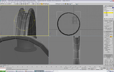
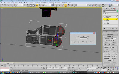
Next I tried to find a tool to enhance the ends of this u shaped link as they should actually be round and the first tool I found that seemed to replicate anything of this nature was the tessellate edges tool:


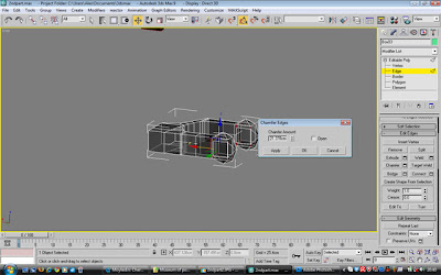
and then using the chamfer tool i was able to add it some more edges to manipulate the shape some more:


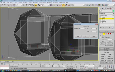
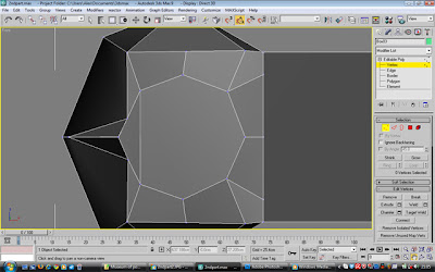
then using the connect edges tool i was able to add in some more edges that allowed me to create an inner circle:


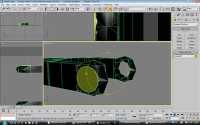
I added a small cylinder to give the effect a metal pin was going through:


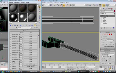
add the metal material created earlier:


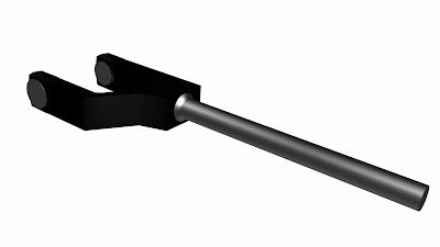
and rendered it so far:


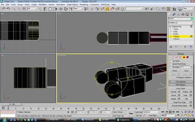
But, wanting perfection and also realising there is a way to achieve not only the same effect but better adn its about 10 times easier was to have deleted the end polygons (the one I just performed all the modifications to) and add two cylinders the same:


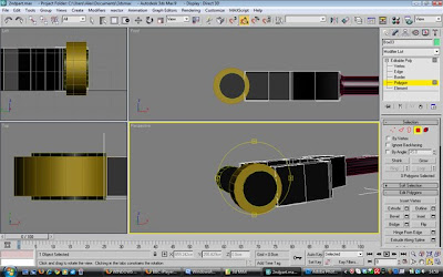
and then adding a bigger cylinder around these ones:


and then joining the bigger cylinders to the box using the vertex weld tool, I came up with this:


Ok so I did take the long way round, but we live and learn. I wont be making that mistake again (hopefully).